The Fab Academy 2014
Digital Fabrication Laboratory. Department of Architecture.
Institute of Technology. EPS-CEU San Pablo CEU University
Adolfo Gutiérrez Sánchez
Architect
The Fab Academy 2014 Digital Fabrication Laboratory. Department of Architecture. Institute of Technology. EPS-CEU San Pablo CEU University |
Adolfo Gutiérrez Sánchez Architect |
|||
| Home | Portfolio | Files | ||
| INPUT DEVICES |
|
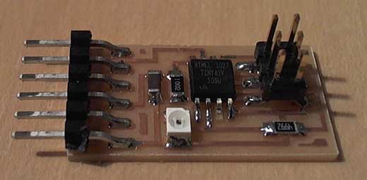
The assignment The assignment for this week was to redesign one of the Input boards. The chosen board was the phototransistor, as I will need it for the final project and I wanted to test it. The whole board was not necessary, because it will be controlled by my Fabduino and I will not need programmer pins neither a microcontroller. |
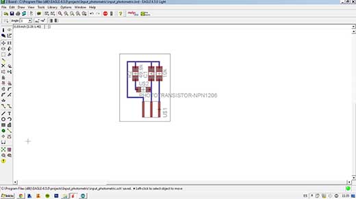
The board design The first step of the assignment was to decide what parts of the board would be necessary and how many of them were not. As i will need to save as much space as possible. I redesigned the whole board in order not not have an additional microcontroller neither its own programming pins, so the board reduces considerably its size and its price aswell. The board is redesigned with Eagle, incorporating just the necessary components: - Phototransistor - 2 resisotors - 1 capacitor
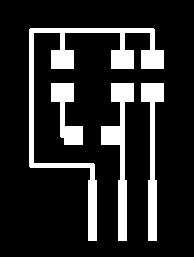
FIXING DESIGN PROBLEMS After I tried to program the board, I realized that there were some components that were not necessary at all, and I had to redesign the whole board with just a Phototransistor and a resistor. |
 |
 |
 |
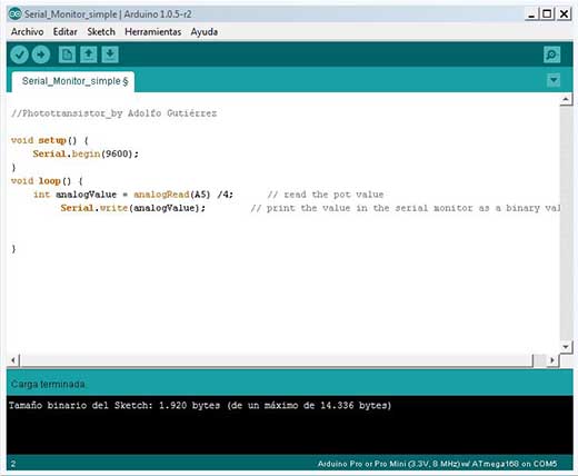
Programming with Arduino I decided that I will just take the data from the phototransistor and bring it into the processing monitor, where I will visualize the data. The Arduino code to be written was very easy: I created a void setup where the port of the Serial Monitor is opened and a Void loop where the data is taken and resent as an analog data into Processing. //Phototransistor_by Adolfo Gutiérrez void setup() {
|
 |
|
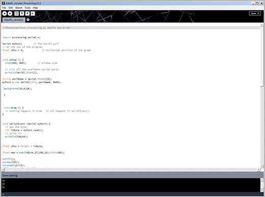
Programming with Processing As the program of the Processing was a little bit more difficult and it was the first time opening this software, it took me longer not just to write the code but to understand the process that Processing is doing through Arduino code. 1. In the first part, Processing tooks the data from Arduino opening the port: import processing.serial.*; Serial myPort; // The serial port is opened 2. In the second part, we set our CANVAS where the data is going to be visualized. All the code contained in a VOID SETUP is going to be fixed and will not vary all along the code: void setup () { // List all the available serial ports String portName = Serial.list()[0]; background(10,4,64); 3. In the thir part, we set the settings and parameters to visualize the data. In my case it will be a circle that varies its diameter in relation of the intensity of the light from the phototransistor. I remapped the data collected from Arduino into a maximum and minimum in order to fit always the circle in the size of my canvas. All the code contained in VOID DRAW and in VOID SERIALEVENT will be changing constantly: void draw () { void serialEvent (Serial myPort) { float yPos = height - inByte; float map = map(inByte,37,200,10,width-200); noFill(); background(10,4,64); } |